
True Position Calculator – Calculate GD&T Tolerance
True Position Calculator
GD&T position tolerance check with optional MMC / LMC bonus tolerance
Deviation ΔX
Deviation ΔY
Radial deviation
Specified tolerance
Bonus tolerance
Total allowed tolerance
Remaining margin
Tolerance used
Material condition
Calculated entirely in your browser. No data is sent or stored. Position tolerance is treated as a cylindrical (diametral) zone with a perpendicular-axis X/Y offset.
This increase occurs because the tolerance zone has a different shape. Coordinate dimensions create a rectangular tolerance zone, whereas GD&T Position uses a diametric tolerance zone. When checking the feature’s location, the inspection process remains the same, with deviations measured along the X and Y directions. However, these two measurements must be combined and converted into a single diametric deviation value.

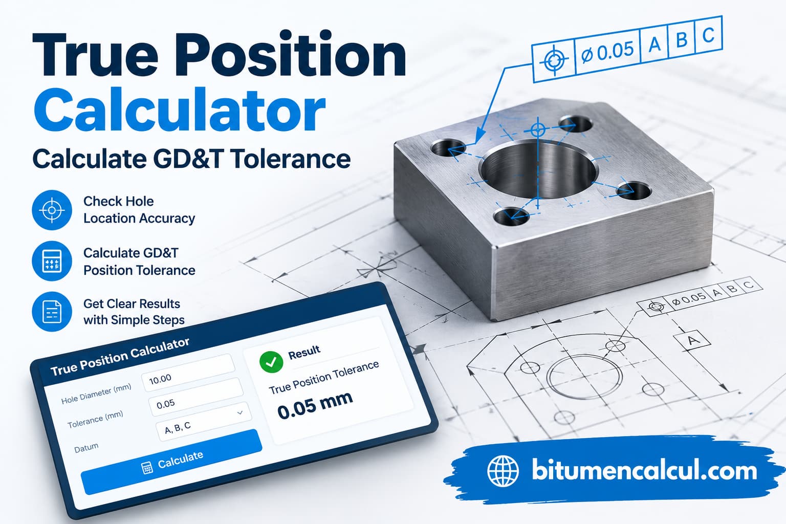
We have developed a convenient true position calculator to simplify this conversion for you.
To get started, enter the required details from your engineering drawing along with the measured values of your feature. The calculator will automatically determine the total position tolerance, account for any applicable bonus tolerance, calculate the position error (diametric deviation value), and show whether the feature meets the specified position requirements. Below the calculator, you’ll also find step-by-step examples explaining how to enter the data and understand the expected results.
How to Calculate True Position with This GD&T True Position Calculator

Our GD&T true position calculator makes it easier to determine the position tolerance of a feature. Follow these steps to use the tool correctly:
- Enter the drawing details: Provide the position tolerance value and the specified material condition from the feature control frame.
- Choose the material condition: If you select MMC or LMC, specify whether the feature is a hole or a shaft. Then, enter the feature size and its corresponding tolerance values.
- Define the true position: Enter the basic dimensions shown on the engineering drawing that locate the feature from the secondary and tertiary datums (typically B and C, although the datum labels may vary).
- Add the actual measurements: Input the dimensions measured from the physical part. If MMC or LMC applies, also enter the feature's actual measured size.
- Review the calculator results: The tool will generate a position offset summary showing:
- Position offset: The distance between the measured location and the true position specified in the drawing.
- Overall position variation: The total positional deviation calculated from the measured values.
- Bonus tolerance: The additional tolerance available when applicable under MMC or LMC.
- Total tolerance: The allowable position tolerance, including any applicable bonus tolerance.
- Tolerance excess or deficit: Indicates how much the actual part exceeds the permitted tolerance or remains within the allowable limit.
By entering the correct drawing specifications and measured values, you can use the calculator to evaluate the feature's true position and check whether it satisfies the specified GD&T requirements.
Formula for Calculating the True Position of a Hole or Shaft
As explained in the previous section, calculating the true position of a hole involves determining the difference between its specified true position and its actual measured location.
Since position tolerance is expressed as a diameter, we first use the distance formula to calculate the radial distance between the true position and the measured position. We then multiply this distance by 2 to obtain the diametric position variation, which can be compared directly with the specified position tolerance.
The formula for calculating the actual position variation (PV), or deviation from the true position, is:
[
PV=2\sqrt{(TB-MB)^2+(TC-MC)^2}
]
Where:
PV— The position variation from the specified true position.TB— The true position of the feature measured from datum B.MB— The actual measured position of the feature on the part from datum B.TC— The true position of the feature measured from datum C.MC— The actual measured position of the feature on the part from datum C.
For a part to pass inspection, its position variation must satisfy the condition (PV \leq TT), where TT represents the total position tolerance. If the drawing does not specify a material condition, the stated position tolerance applies directly, regardless of the feature's actual size. In this situation, the total position tolerance is simply equal to the specified position tolerance.
However, when a material condition such as MMC or LMC is specified, an additional bonus tolerance may be available depending on the actual size of the feature. The following sections explain how to calculate the total true position tolerance under these conditions.
What Are Maximum and Least Material Conditions?
When a feature's size allows it to contain the greatest possible amount of material, it is said to be at maximum material condition (MMC). For internal features, such as holes, MMC occurs when the hole has its smallest permitted diameter. For external features, such as shafts, it occurs when the shaft has its largest permitted diameter.
In contrast, least material condition (LMC) refers to the feature size that contains the smallest possible amount of material. For an internal feature, such as a hole, LMC occurs when the hole reaches its largest permitted diameter. For an external feature, such as a shaft, LMC occurs when the shaft reaches its smallest permitted diameter.
Material Conditions: Calculating Bonus Tolerance for True Position
In many cases, the position tolerance depends on the actual size of a feature. For example, a larger hole may allow greater variation in the location of its center, while a smaller hole may require the center to remain within a tighter tolerance. When the hole is larger than its maximum material condition (MMC) size, the additional allowable variation is known as bonus tolerance, which provides more flexibility in the feature's true position.
In other situations, the tolerance requirements may work in the opposite way. A feature may be allowed greater positional variation when its size is smaller, while a larger feature may need to meet stricter tolerance limits.
Engineers define whether position tolerance depends on feature size by using a material condition modifier in the feature control frame. There are three possible conditions:
Ⓜ— Maximum material condition (MMC).Ⓛ— Least material condition (LMC).- No modifier (RFS) — The position tolerance applies regardless of the feature's actual size.
The applicable material condition determines how the allowable position tolerance is evaluated and whether any additional bonus tolerance can be applied. In the following sections, we'll explain how to calculate the bonus tolerance for true position under each condition.
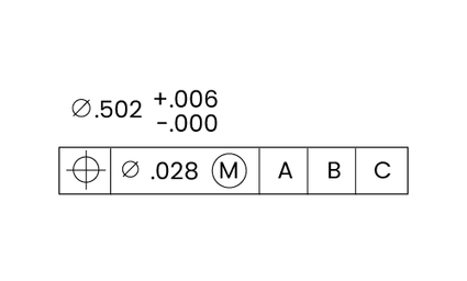
To see how true position is calculated under maximum material condition (MMC), let's revisit the previous position tolerance example. The hole on the actual part can have a diameter ranging from 0.502 in to 0.508 in. Since the engineering drawing includes the Ⓜ symbol for MMC, the hole receives additional position tolerance as its diameter increases beyond the MMC size.
The tables below show how the actual hole diameter affects the bonus tolerance and total position tolerance.
True Position Tolerance at MMC
| Actual hole size (in) | MMC size (in) | Bonus tolerance (in) | Position tolerance (in) | Total tolerance (in) |
|---|---|---|---|---|
| 0.502 | 0.502 | 0.000 | 0.028 | 0.028 |
| 0.503 | 0.502 | 0.001 | 0.028 | 0.029 |
| 0.504 | 0.502 | 0.002 | 0.028 | 0.030 |
| 0.505 | 0.502 | 0.003 | 0.028 | 0.031 |
| 0.506 | 0.502 | 0.004 | 0.028 | 0.032 |
| 0.507 | 0.502 | 0.005 | 0.028 | 0.033 |
| 0.508 | 0.502 | 0.006 | 0.028 | 0.034 |
If the drawing specifies least material condition (LMC) instead, the LMC size for this hole is 0.508 in. In this case, the bonus tolerance increases as the actual hole diameter decreases below the LMC size.
True Position Tolerance at LMC
| Actual hole size (in) | LMC size (in) | Bonus tolerance (in) | Position tolerance (in) | Total tolerance (in) |
|---|---|---|---|---|
| 0.502 | 0.508 | 0.006 | 0.028 | 0.034 |
| 0.503 | 0.508 | 0.005 | 0.028 | 0.033 |
| 0.504 | 0.508 | 0.004 | 0.028 | 0.032 |
| 0.505 | 0.508 | 0.003 | 0.028 | 0.031 |
| 0.506 | 0.508 | 0.002 | 0.028 | 0.030 |
| 0.507 | 0.508 | 0.001 | 0.028 | 0.029 |
| 0.508 | 0.508 | 0.000 | 0.028 | 0.028 |
If the drawing has no material condition modifier, regardless of feature size (RFS) applies. The position tolerance then remains 0.028 in for every permitted hole diameter, with no bonus tolerance.
The bonus tolerance formulas for each material condition are:
For maximum material condition (MMC):
[
\text{Bonus}_{MMC}=|\text{MMC size}-\text{Actual size}|
]
For least material condition (LMC):
[
\text{Bonus}_{LMC}=|\text{LMC size}-\text{Actual size}|
]
For regardless of feature size (RFS):
[
\text{Bonus}_{RFS}=0
]
Therefore, when calculating true position tolerance, you must account for the material condition specified in the drawing. Add any applicable bonus tolerance to the stated position tolerance to determine the total allowable position tolerance:
[
\boxed{TT=\text{Position tolerance}+\text{Bonus tolerance}}
]
This total tolerance is then compared with the calculated position variation to determine whether the feature meets the drawing requirements.
FAQs
Conclusion
A GD&T true position calculator makes it easier to calculate positional deviation, determine bonus tolerance under MMC or LMC, and find the total allowable position tolerance. By entering the drawing dimensions, datum references, and actual feature measurements, you can quickly check whether a hole or shaft meets the specified requirements. This tool simplifies true position calculations, saves time during inspection, and helps engineers achieve accurate and reliable dimensional verification.
Read More: